By: Will Brown (UGA Extension, Appling County), Jennifer Miller (UGA Extension, Jeff Davis County), Sarah Beth Thompson, and Wesley Porter
While planting is going full speed there are many planters that have insecticide hoppers on the back of the row units, and it is critical that these systems are calibrated. Depending on which crop you are planting the chances are high that you will be applying one of these products. While input costs are at an all-time high, we need to ensure products such as these insecticides are properly calibrated so that we are hitting our target rates to ensure adequate efficacy. We want products to work so we must eliminate under applications and ensure we are not wasting products by overapplying.
Safety
When performing any calibrations it is important to follow all labeled PPE suggestions. It is especially important when working with these types of products as they can cause extreme illness and potentially death if mishandled. Make sure you are wearing gloves, a mask and proper eye protection during the calibration procedure. Ensure that you thoroughly wash your hands after calibration and handling any of these products, especially before eating or drinking anything or even touching your face or using the restroom etc. We cannot stress enough how dangerous secondary contact of these products is. Additionally, the SW and SE Extension district offices do offer blank products for you to use during calibration. However, remember that the actual product has been in the insecticide hoppers, thus there will be some cross contamination so do not let your guard down and not use PPE or wash properly afterward.
Calibration Options
When performing insecticide calibrations there are many options on how to complete the calibration procedure. The next few sections will outline those. It is important to note what type of planter you are calibrating and if it is ground driven, hydraulic, or electronic. If you are working with a John Deere planter with standard ground drive that has a high and a low range for seeding rate, these ranges are connected to the output on the insecticide boxes, thus, you may need to put the drive into the high range and adjust the seed population accordingly.
Dynamic Calibration: This type or calibration, as it implies, involves the equipment moving through the field.
1. Catch the product:
- Flag off a known distance (and since most of the charts use 200 ft that is suggested!!) and attach some sort of catch device on either the tube or the outlet on the insecticide hopper and have the operator drive the flagged distance at their normal operating speed.
2. Determine rate applied:
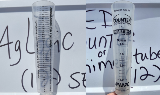
- Once the distance is completed take the material from the tube and weigh it or pour it into the appropriate calibration tube. If you are using product specific catch tubes, be sure you are using the correct tubes for the product you are calibrating for.
- The amount of product applied from each hopper box should be weighed individually, not cumulatively, to ensure each hopper box is applying product evenly across the planter.
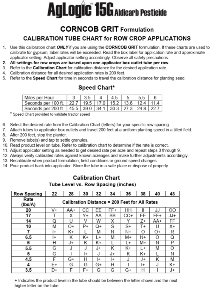
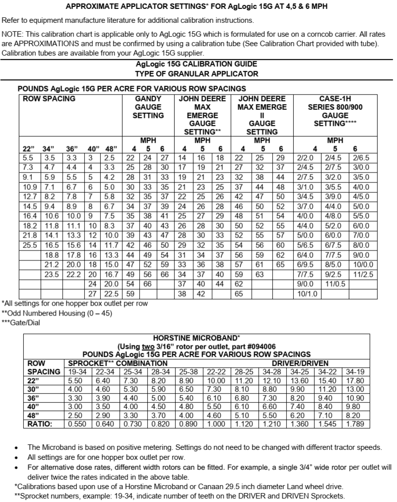
- Use the appropriate calibration sheets included at the end of this newsletter to determine the rate applied. There are separate calibration sheets depending on which product you are applying.
- Note: The AgLogic calibration chart and catch tubes uses a lettering system that correlates to the lbs/ac of product applied. The Counter/Thimet calibration chart and catch tubes uses a weight (oz.) system that correlates to the lbs/ac of product applied.
3. Adjust the gate opening accordingly:
- The opening is adjusted by increasing or decreasing the number of the gauge setting on the hopper. Increasing the number increases the amount of product applied and decreasing the number reduces the amount of product applied. It is not uncommon for hoppers to be set on different gauge settings.
4. Repeat this process until you can achieve within an acceptable tolerance of the targeted rate.
Static Calibration
- In most cases static or sitting still calibration is much easier than moving for many reasons. There are two ways to complete a static calibration.
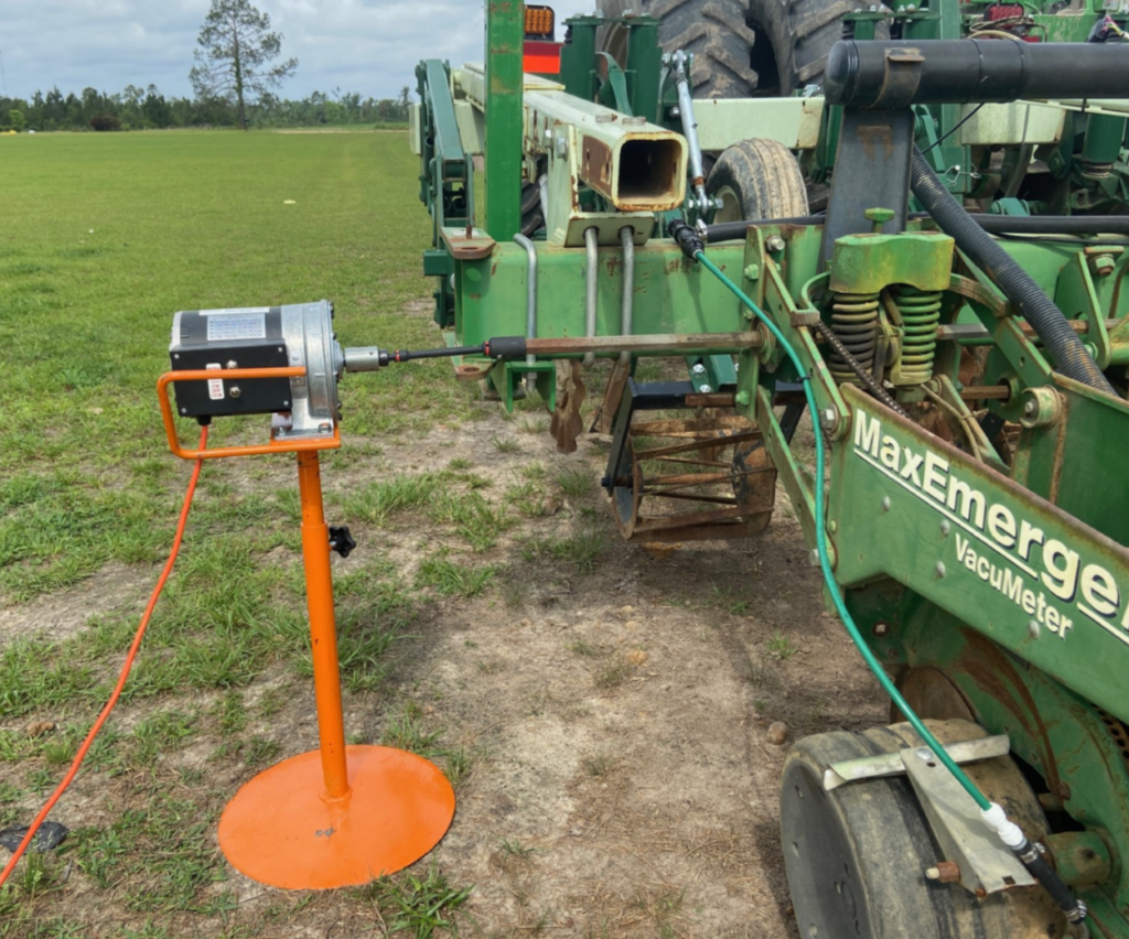
- Static calibration utilizing an external drive motor: This type of calibration seems to be one of the most popular at the time. Both UGA and some industry representatives have external drive motors that can be attached to the drive shaft on the planter.
1. Disconnect the drive train on the planter and connect the motor to the drive bar as shown in the figure below:
- The operator must disconnect the drive train on the planter so that the motor can turn only the row units and insecticide boxes. Ensure that when you attach the drive motor to the drive shaft on the planter that it is spinning in the correct direction for the planter to operate in forward, the drive shaft should spin clockwise, but can vary based on model, so check this before attaching the motor.
2. Catch the product:
- Have your catch tubes in place and run the motor for the appropriate catch time, which is determined by the desired travel speed and calibration distance.
- Each of these motors has an associated chart that lets you know the corresponding ground speed to the motor RPM. Below are three charts that provide the time required to catch the product for corresponding speeds for both 200, 400, and 500 ft calibration distance.
Here are the three charts that provide the time required to catch the product for corresponding speeds for both a 200, 400, and 500 ft calibration distance:
Ground Speed in MPH for Catch Time in Seconds per 200 ft (CLICK ARROW FOR DROP DOWN)
| Speed (MPH) | Speed (ft/s) | Catch Time (sec) |
| 1.0 | 1.5 | 136.3 |
| 1.5 | 2.2 | 90.9 |
| 2.0 | 2.9 | 68.2 |
| 2.5 | 3.7 | 54.5 |
| 3.0 | 4.4 | 45.4 |
| 3.5 | 5.1 | 39.0 |
| 4.0 | 5.9 | 34.1 |
| 4.5 | 6.6 | 30.3 |
| 5.0 | 7.3 | 27.3 |
| 5.5 | 8.1 | 24.8 |
| 6.0 | 8.8 | 22.7 |
| 6.5 | 9.5 | 21.0 |
| 7.0 | 10.3 | 19.5 |
| 7.5 | 11.0 | 18.2 |
| 8.0 | 11.7 | 17.0 |
| 8.5 | 12.5 | 16.0 |
| 9.0 | 13.2 | 15.1 |
| 9.5 | 13.9 | 14.4 |
| 10.0 | 14.7 | 13.6 |
Ground Speed in MPH for Catch Time in Seconds per 400 ft (CLICK ARROW FOR DROP DOWN)
| Speed (MPH) | Speed (ft/s) | Catch Time (sec) |
| 1.0 | 1.5 | 272.7 |
| 1.5 | 2.2 | 181.8 |
| 2.0 | 2.9 | 136.3 |
| 2.5 | 3.7 | 109.1 |
| 3.0 | 4.4 | 90.9 |
| 3.5 | 5.1 | 77.9 |
| 4.0 | 5.9 | 68.2 |
| 4.5 | 6.6 | 60.6 |
| 5.0 | 7.3 | 54.5 |
| 5.5 | 8.1 | 49.6 |
| 6.0 | 8.8 | 45.4 |
| 6.5 | 9.5 | 41.9 |
| 7.0 | 10.3 | 39.0 |
| 7.5 | 11.0 | 36.4 |
| 8.0 | 11.7 | 34.1 |
| 8.5 | 12.5 | 32.1 |
| 9.0 | 13.2 | 30.3 |
| 9.5 | 13.9 | 28.7 |
| 10.0 | 14.7 | 27.3 |
Ground Speed in MPH for Catch Time in Seconds per 500 ft (CLICK ARROW FOR DROP DOWN)
| Speed (MPH) | Speed (ft/s) | Catch Time (sec) |
| 1.0 | 1.5 | 340.8 |
| 1.5 | 2.2 | 227.2 |
| 2.0 | 2.9 | 170.4 |
| 2.5 | 3.7 | 136.3 |
| 3.0 | 4.4 | 113.6 |
| 3.5 | 5.1 | 97.4 |
| 4.0 | 5.9 | 85.2 |
| 4.5 | 6.6 | 75.7 |
| 5.0 | 7.3 | 68.2 |
| 5.5 | 8.1 | 62.0 |
| 6.0 | 8.8 | 56.8 |
| 6.5 | 9.5 | 52.8 |
| 7.0 | 10.3 | 48.7 |
| 7.5 | 11.0 | 45.4 |
| 8.0 | 11.7 | 42.6 |
| 8.5 | 12.5 | 40.1 |
| 9.0 | 13.2 | 37.9 |
| 9.5 | 13.9 | 35.9 |
| 10.0 | 14.7 | 34.1 |
3. Determine rate applied:
- Once you have caught the product for the appropriate time, determine the applied rate by using the same steps listed in the step for Determine rate applied in the Dynamic Calibration section.
4. Adjust the gate opening accordingly:
- See this step in Dynamic Calibration for specific instructions.
5. Repeat this process until you achieve the targeted rate.
- Static calibration utilizing SmartBoxes or other control systems: The John Deere SmartBoxes provides the user with the capabilities to do a static calibration without the need for an external drive motor.
Static Calibration Utilizing SmartBoxes or Similar Control System (the following steps were copied from a JohnDeere SmartBox manual, if you have another type of system, follow that manufacturer recommended calibration process, it should be similar to this but may not have the exact same steps)
- The John Deere SmartBoxes provides the user with the capabilities to do a static calibration without the need for an external drive motor.
- Go into the controller in the tractor cab and set up the test speed, chemical type, and target application rate.
- From SMARTBOX Calibration Guide:
- Number the calibration tubes to correspond with the number of planter rows.
- Confirm that the scale used for weighing the catches is set to ounces and placed on a flat surface out of the wind.
- System Calibration:
- From the Main Menu, select SYSTEM CALIBRATION., Using the arrow keys, enter the test speed equal to the expected planting speed (e.g., 5.5 mph). Press ENTER to continue.
- Meter Calibration:
- Select METER CALIBRATION. Using the arrow keys, scroll to select the chemical being used during operation. Press ENTER.
- Choose the desired calibration distance (options are 500’ or 1000’).
- Using the arrow keys, enter the target catch amount corresponding to the desired application rate. The controller will be preset at 42.5 grams/500’ and will allow values between 5.0 to 300.0 grams/500’.
- Press ENTER to continue.
- Catch Test: Install a catch tube under each meter and discharge opening.
- Press START to begin the catch test. The TIME REMAINING value will indicate the seconds required to plant 500 or 1000 feet of a row at the selected ground speed. The catch test will end automatically once the TIME REMAINING value counts down to zero.
- Weigh the amount caught for each row (excluding the tare weight). Enter the caught amount for each row using the arrows and press NEXT ROW to move to the next row.
- If all catch amounts are within 5% of the target weight, press MAIN MENU to return to the SYSTEM CALIBRATION SET screen. If any catch weight is outside the 5% calibration variance, conduct another catch test by returning to the previous steps and repeating the process.
- Final Steps: Recalibrate after the first set of transfer containers are empty, when application rates are not accurate, or if a different chemical will be used. Keep a record of all calibration data for future reference.