By Chance Warren and Wesley Porter
With planting season fast underway it is crucial that dry fertilizer spreaders are properly calibrated both in application rate and distribution prior to applications of lime and fertilizer. Calibrations are unique to each material tested due to varying density and material shape, so it is imperative that calibrations are performed prior to spreading a new material and new material blends. This should be completed for new materials as well as every year prior to spreading to ensure the equipment is up to par to the season. Calibration is essential for ensuring the right rate is applied along with a uniform application. The link to the step-by-step guide to calibrating dry broadcast fertilizer applicators is in the red button below. This article makes note of several high points for the process and some potential issues that may need to be addressed.
Calibration Checklist
Calibration should be conducted while utilizing a calibration kit containing collection pans of a known area, baffle for each pan, a measuring tape capable of reaching 100 ft, vials for each respective pan, a test tube rack, tachometer, a scale to read density in lbs./cubic ft, and a precise scale capable of reading in grams.
Prior to conducting a calibration test, check for any worn or damaged parts on the spinner disc as well as the buggy itself along the frame. Salts from prior fertilizer applications may expediate damage or corrosion of the equipment. Ball bearings and other fittings can be damaged or corroded and may be lost when the disc is operated.
General Procedures for Calibration
Field or test conditions should be flat and have wind speeds no greater than 10 mph to ensure a uniform application of materials. Given uneven terrain may skew results by throwing material more to the right or left side of the swath. The same is true for wind skewing results and material deposition based on wind direction.
When performing a calibration ensure the spinner discs are operating at the desired RPM (preferably around the 550-650 RPM). Operating at higher RPMs, especially over 1,000, will result in granules being broken and or turned into a powder. This not only affects the uniformity of application due to the uneven material sizes but will affect the efficacy of application as well.
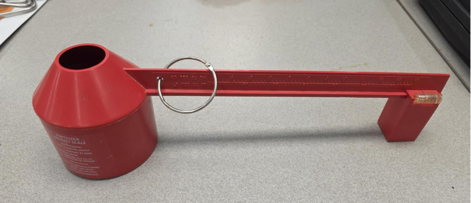
Above is the scale used to calculate the density of the tested material which will be used with the chart found on the spreader to calculate the target rate based on said density and swath width. Adjustments to the gate may be made to the gate to then account for the desired target rate from the chart.
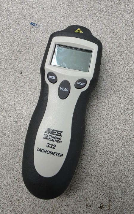
Pictured is a tachometer that when used with reflective tape can be used to estimate the speed of the spinner discs in RPM. Note that the pictured model has a limit of 1,000 RPM, so readings that give an error or no reading at all may be attributed to the fact that the device is unable to read the excessive speed. Additionally, excess light in the field may oversaturate the reflective tape and cause no reading.
Next catch pans may be laid out according to the desired swath width. However, there should always be a pan at the center directly under the tractor as well as a pan 6 ft to both the left and right of the center to allow for the tires of the tractor to pass through. Keep in mind equipment spacing to avoid pans being ran over.
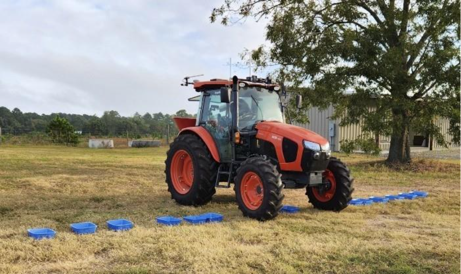
The above image highlights the placement of pans in accordance with a 36 ft swath and illustrates the extra spacing to allow for the tractor to pass.
Ground-Driven vs. Hydraulic
No difference exists between the two in the calibration steps; however, more variables are in play with a ground driven rig than that of a hydraulic system. As the same steps will be taken just now with a ground driven rig, we must factor in other variables such as tractor speed/gear as well as PTO RPMs. When operating a ground-driven system, it is crucial to change one variable at a time when making changes in order to isolate an issue and rectify it in the calibration process.
Hydraulic systems also make note of all tractor and spreader parameters but are easier to operate and manage on the fly compared to the ground-driven counterpart.
Correcting Non-Uniform Spread Patterns
Uniform applications are needed to ensure that the proper rate is applied across the effective swath. Given the rate tapers off on the edges of the swath, the corresponding pass will have overlap that will rectify this under-application and bring it back to the target rate. A singular pass is perfect for calibration as it should highlight the effective swath width that eventually tapers off on the edges to account for the corresponding pass or overlap. With this overlap bringing both the rate and uniformity to its desired point.
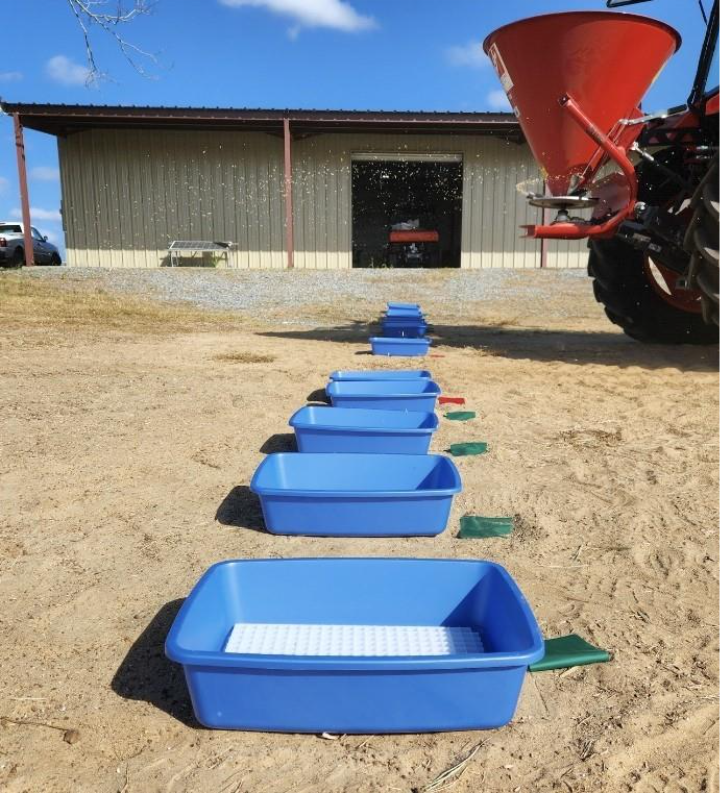
The image highlights the importance of running the spreader system past the collection pans to ensure the proper collection of applied material. Stopping the spreader prematurely will skew results by not accounting for the full rate being applied.
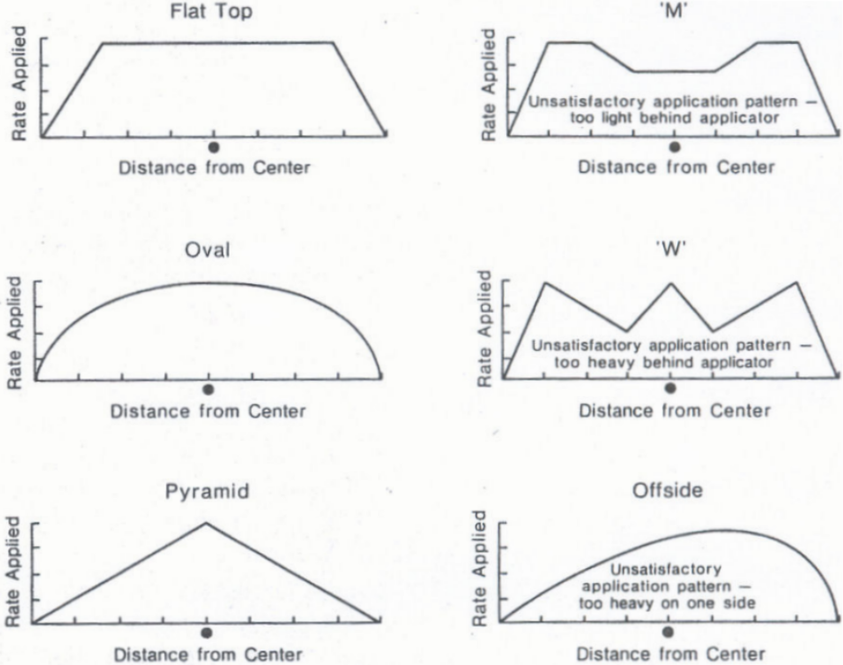
The above image highlights patterns that are acceptable for uniform distribution (left) and those that will not yield a uniform distribution. With those on the right attributed to not enough material in the center, too much material in the center, and a shift in gravity leaning either left or right respectively.
Additional Things to Consider
The skills of the operator are critical as their ability to spread at a uniform pace in terms of speed and spinner disc RPMs will also influence the uniformity of the distribution across the desired swath. It is important to note that yes, the faster you go and the larger swath you have the more ground you can cover, but you sacrifice uniformity in doing so. Resulting in a waste of time and money for both fuel and fertilizer costs due to uneven applications that will require an additional application to be corrected.
In cases where RPMs were exceeding 1,000 RPM, the material was prone to shattering and dusting resulting in issues such as streaking and the inability to establish an effective swath width. Furthermore, no effective swath width could be determined given the destruction of material and the deposition of material past the desired swath width.